Home > Introduction > Tutorial > Tutorial sub structure
Sub Structure tutorial VolturnUS floater 15 MW
Introduction
Floating Offshore Wind Turbines (FOWT) represent complex systems with couplings between their different components submitted to hydrodynamic and aerodynamic loads.
On a hydrodynamic point of view, FOWT are at the edge between the small and large body assumptions depending on the incident wave (small body means \(\lambda/D>5\) where \(\lambda\) is the wavelength and \(D\) the body dimension). As a consequence, the hydrodynamic loads acting on the floaters may be as well represented by a Morison type formulation, a diffraction theory approach or a mix of them. Every approach has advantages and drawbacks. The main idea here is to combine Morison’s formulation and diffraction/radiation theory. That means that the floater’s hull will be modelled with beam finite elements in DeepLines WIND but the hydrodynamic loads on the beam elements will be computed in two ways:
-
A Morison formulation for drag loads,
-
A diffraction/radiation theory approach for hydrostatic loads.
To do this, substructures are defined to divide the floater’s hull into different slices along the different members. These substructures are associated with “sub-HDB” files that can be loaded in the Deeplines WIND model to provide linear loading on the beam elements, as illustrated in Figure 1.
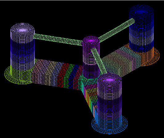
Figure 1 : Substructures HDB files illustration.
Purpose of tutorial
The aim of this tutorial is to detail the various steps involved in creating a substructure model using an Excel file. The first step is to create the mesh of the structure. The mesh should be clearly defined because once it is defined it will not be changed in the next steps. The second step is to create a beam model derived from the first step. All beam element properties and substructure groups are defined. Any required fairleads can also be defined. Once the excel file is done, it is possible to drag and drop it in DLW (for more details, see Excel file). Then, the HDB substructures can be created in DLW. This document details the different steps taken to create a derived semi-submersible UMaine VolturnUS, which was presented by the N-REL in a dedicated report. The model presented is defined with a simplified turbine. It’s a steel floater for a 15MW turbine. The main dimension between the NREL model and the derived model are presented here after.
The sub-structure could be flexible (the beams), so that the stress at the connections and into the beams can be calculated. A HDB is define for each sub-structure of the floating platform and all the hydrostatic, diffraction/radiation are integrated in a first place at these elements before to be transported to the global reduction point. A simple HDB is completely rigid, with no stress calculation within the floating platform. All the hydrostatic, diffraction/radiation are integrated directly to the reduction point.
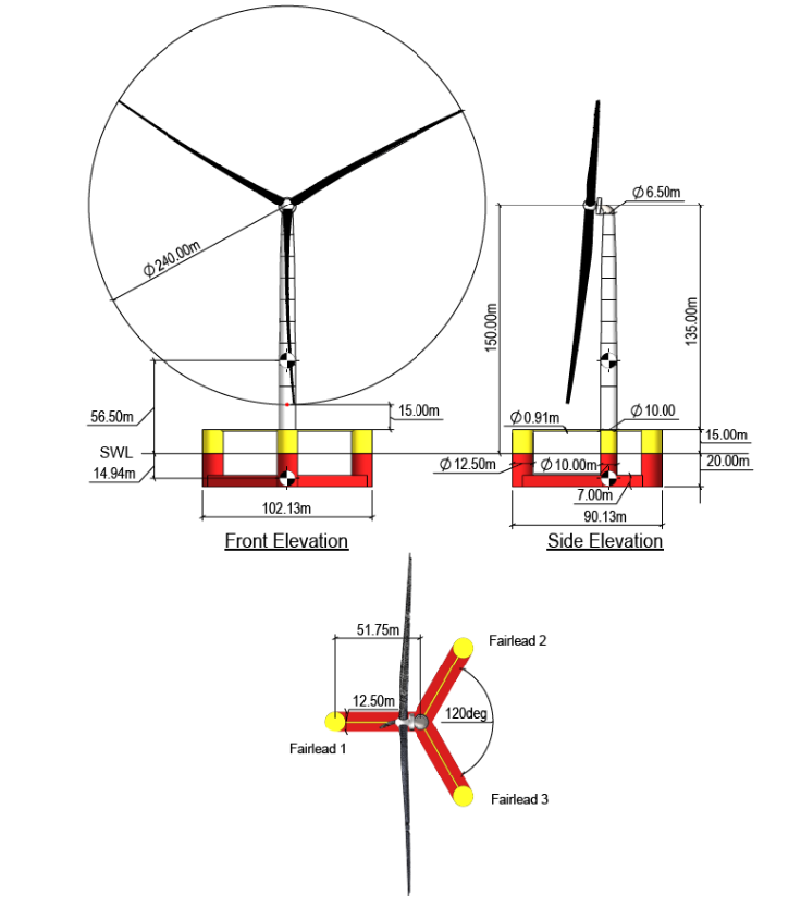
Figure 2 : General arrangement of the Volturn US from NREL.
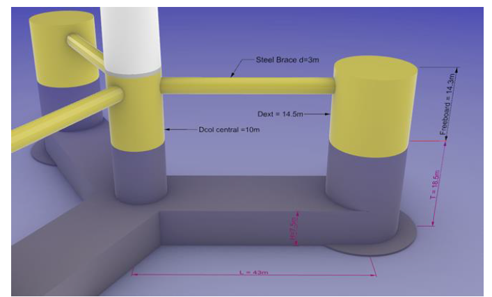
Figure 3 : General arrangement of the derived Volturn US.
| Paramètre | Valeur | Unité |
|---|---|---|
| Depth of platform base below SWL (total draft) | 18.5 | m |
| Elevation of columns above SWL | 14.3 | m |
| Radius between main column and external columns | 43 | m |
| Diameter main column | 10 | m |
| Thickness of main column | 40 | mm |
| Diameter of external columns | 14.5 | m |
| Thickness of external columns | 40 | mm |
| Diameter of skirts | 21.75 | m |
| Height of skirts | 400 | mm |
| Length of braces | 30.75 | m |
| Diameter of braces | 3 | m |
| Thickness of braces | 30 | mm |
| Section of bottom pontoons HxW | 7.5 x 14.5 | m² |
| Thickness of bottom pontoons | 100 | mm |
DeepLines Model overview
The Volturn US is divided into several beam sections in order to size them. Each section has specific properties and are affected by hydrodynamic and/or aerodynamic loads, mooring loads, etc... However, some parts of the model are considered to be rigid as they are complex to model with beam properties. That’s the case for each bottom columns including the skirts. These parts are the connections between the columns and the pontoons. A local FEM model must be used to size them. To clearly identify the rigid part of the model, the connections are represented with their own mesh as shown in Figure 4. The Volturn US set up is defined with spring moorings and simplified turbine.
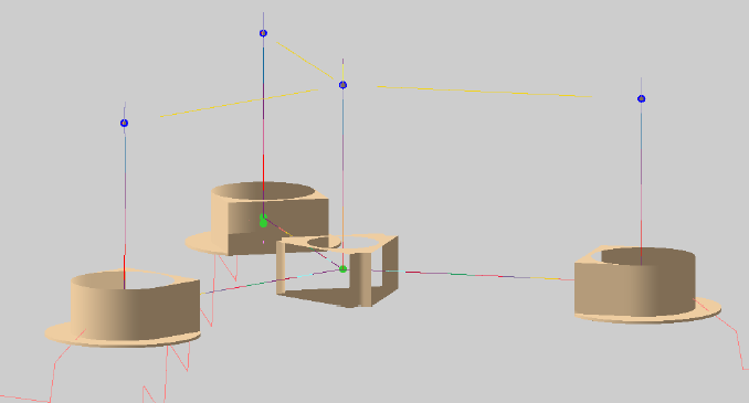
Figure 4 : Connections mesh.
To build the Deeplines model a model excel file available in the Deeplines installation folder is used. Beam model is defined in the excel. The excel file is presented in figure 5.
• The first sheet defines the name of the dsk and the colour code of the excel cells.
• Several sheets representing the option in the Deeplines GUI (line sections, line properties, calculation properties, etc..). To build the Volturn US, the user must navigate through several sheets. Not all the sheets have to be complete, only the necessary ones, that will be defined in the next steps. The sheets don’t used can be deleted. The user can create other sheets if needed until that the name is different from those in the model. Deeplines only reads certain sheet names and ignores others.
The Deeplines section is divided into 3 parts:
• Beam model set up
• Properties definition
• Substructure definition
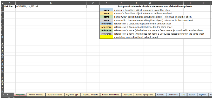
Figure 5 : Excel sheet example.
The Volturn US is divided in several substructures as follow:
• Pontoons are divided into 8 substructures
• Columns are divided into 5 substructures
• Braces account for 1 substructure (they are not expected to be in contact with sea water)
• Each base column with skirt (or not) account for 1 rigid substructure.
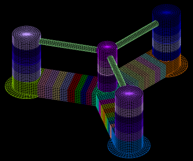
Figure 6 : Volturn US Substructures.
Requirements: it is assumed that the user is able to generate a hydrodynamic mesh
Beam model set up
-
1 Give a name to the model in the sheet “Deeplines” cell B2
-
2 In the sheet “Line” define all the lines needed to build the Volturn US. For the pontoons a specific “Steady internal fluid reference” is defined corresponding to the ballast. The ballast is defined in the next section.
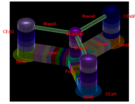
Figure 7 : Lines definition.
| Name | Straight pipe | Steady internal fluid reference |
|---|---|---|
| CCentral | no | DefaultFluid |
| CExt1 | no | DefaultFluid |
| CExt2 | no | DefaultFluid |
| CExt3 | no | DefaultFluid |
| Pont1 | no | BallastPon |
| Pont2 | no | BallastPon |
| Pont3 | no | BallastPon |
| Skirt1 | no | DefaultFluid |
| Skirt2 | no | DefaultFluid |
| Skirt3 | no | DefaultFluid |
| Brace1 | no | DefaultFluid |
| Brace2 | no | DefaultFluid |
| Brace3 | no | DefaultFluid |
| aero_WTG | no | DefaultFluid |
| Tower | no | DefaultFluid |
- 3 In the sheet “Rigid body” define all the required rigid bodies as shown in the Figure 8 . As the turbine modelling is a simplified one, a rigid body is defined instead of a full BEM model. The rigid bodies are connected to the “Fairlead reference” are defined in the next step.
It is not a mandatory to define the coordinates of rigid bodies as they are connected to another element. For instance, “RG_WTG_simple” is connected to the tower. So, its coordinates are derived from the tower ending defined in the “Section” sheet. The only mandatory is consistency between the two sheets, the coordinates must appear in at least one of them.
It's possible to apply a mesh to the rigid bodies, an imported mesh or a drawing mesh (it’s not a mandatory).
| Name | X (m) | Y (m) | Z (m) | Linked to reference | Attach Point reference | Connection type | Connection reference | Fairlead reference | Mesh file | Center of mesh |
|---|---|---|---|---|---|---|---|---|---|---|
| RB_BaseCC | 0 | 0 | -14.75 | FL_RB_BaseCC | $CUR_PATH\Mesh\rigidCC.DAT | Mesh | ||||
| RB_BotCol1 | 43 | 0 | -14.75 | FL_RB_BotCol1 | $CUR_PATH\Mesh\rigidCol1.DAT | Mesh | ||||
| RB_BotCol2 | -21.5 | 37.339 | -14.75 | FL_RB_BotCol2 | $CUR_PATH\Mesh\rigidCol2.DAT | Mesh | ||||
| RB_BotCol3 | -21.5 | -37.339 | -14.75 | FL_RB_BotCol3 | $CUR_PATH\Mesh\rigidCol3.DAT | Mesh |
| Name | X (m) | Y (m) | Z (m) | Linked to reference | Attach Point reference | Connection type | Connection reference | Fairlead reference | Length (m) | Width (m) | Height (m) |
|---|---|---|---|---|---|---|---|---|---|---|---|
| RB_TopCC | 0 | 0 | 11.3 | FL_RB_TopCC | 0.5 | 0.5 | 0.5 | ||||
| RB_TopCol1 | 43 | 0 | 11.3 | FL_RB_TopCol1 | 0.5 | 0.5 | 0.5 | ||||
| RB_TopCol2 | -21.5 | 37.339 | 11.3 | FL_RB_TopCol2 | 0.5 | 0.5 | 0.5 | ||||
| RB_TopCol3 | -21.5 | -37.339 | 11.3 | FL_RB_TopCol3 | 0.5 | 0.5 | 0.5 | ||||
| RG_WTG_simple | Tower | YawB | User-defined | UDC_0 | FL_RG_WTG_simple | 10 | 3 | 1 |
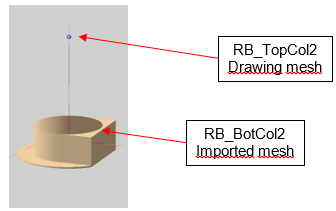
Figure 8 : Rigid Body definition.
- 4 In the “Fairlead” sheet create all the fairlead associated to a rigid body, the floater or the “Sea&Ground”. The fairleads are shown in APPENDIX 1.
Note
The object reference “Volturn_Floater” has not yet been created. But it will in the substructure section §2.4.
- 5 Now that all the points are defined, in the “Section” sheet create all connections between beams, rigid bodies and internal segment of beams. The columns to be defined are shown in APPENDIX 2. The main objective of this part is to split the lines and create different sections of them. Their properties are defined in “Segment sheet” in the next steps. For instance, 8 sections are defined for the line "CCeneral":
• The first section is a specific one connected to the rigid body “RB_BaseCC” this segment is only used in the model to assign hydrodynamic loads (Morison’s forces).
• The other sections split the central column into 7 parts from the rigid body “RB_BaseCC” to the bottom tower using intermediate connections. The connection between a beam and a rigid body must be defined with a specific property in “connection type”. The same “connection type” is used throughout the model, that’s why the “connection reference” is the same.
• The intermediate connections are “line to line”, so there is not connection type requirement, but the user must define the intermediate points (their names and their positions with respect to the coordinates of the origin system).
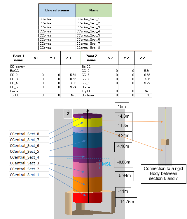
Figure 9 : Section definition.
- 6 In the “Connection” sheet create a user defined connection used in the “Section” sheet. The spring properties used for the mooring are also defined in this sheet.
| User-defined connection name | BC Translation | BC X Translation | BC Y Translation | BC Z Translation | BC Rotation | BC X Rotation | BC Y Rotation | BC Z Rotation |
|---|---|---|---|---|---|---|---|---|
| UDC_0 | yes | Constrained | Constrained | Constrained | yes | Constrained | Constrained | Constrained |
| Spring connection name | Spring unstreched length (m) | Linear stiffness (N/m) |
|---|---|---|
| Spr_Moor | 48900 |
-
In the “Segment” sheet apply one or multiple segments to each section defined in the “Section” sheet. Define the length of the segments, the number of elements (or target spacing) and the segment type reference (see APPENDIX 3). Note that a section can be composed of several segments, but a section must be defined by at least one segment. Be careful when defining the length of the segments. The length should be consistent with the node positions defined in the “Section” sheet. Otherwise, irrelevant internal constraints will appear in the floater model. The segment type references are defined in the next section §2.3
-
In the “Link” sheet define the 3 spring mooring lines and their parameters.
| Name | Type | Connection link properties reference | X1 | Y1 | Z1 | Linked to 1 reference | Attach point 1 reference | Connection 1 type | Connection 1 reference | X2 | Y2 | Z2 | Linked to 2 reference |
|---|---|---|---|---|---|---|---|---|---|---|---|---|---|
| Spring1 | Spring | Spr_Moor | 50.25 | -16.5 | RB_BotCol1 | Mooring | User-defined | UDC_0 | 114.85 | 0 | -59.15 | Anchored | |
| Spring2 | Spring | Spr_Moor | -25.125 | 43.618 | -16.5 | RB_BotCol2 | Mooring | User-defined | UDC_0 | -57.425 | 99.229 | -59.15 | Anchored |
| Spring3 | Spring | Spr_Moor | -25.125 | -43.618 | -16.5 | RB_BotCol3 | Mooring | User-defined | UDC_0 | -57.425 | -99.229 | -59.15 | Anchored |
- In the “Group” sheet define the different group especially for the floater and the mesh of the floater. They will be used for the next step.
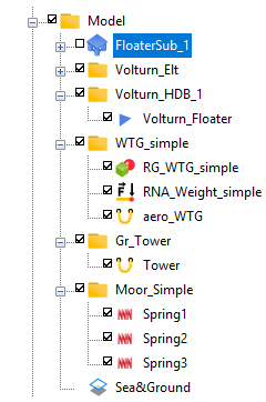
Figure 10 : Group definition in DLW interface.
| Name | Component reference |
|---|---|
| Volturn_Elt | CCentral |
| Volturn_Elt | CExt1 |
| Volturn_Elt | CExt2 |
| Volturn_Elt | CExt3 |
| Volturn_Elt | Pont1 |
| Volturn_Elt | Pont2 |
| Volturn_Elt | Pont3 |
| Volturn_Elt | Skirt1 |
| Volturn_Elt | Skirt2 |
| Volturn_Elt | Skirt3 |
| Volturn_Elt | Brace1 |
| Volturn_Elt | Brace2 |
| Volturn_Elt | Brace3 |
| Volturn_Elt | RB_BaseCC |
| Volturn_Elt | RB_BotCol1 |
| Volturn_Elt | RB_BotCol2 |
| Volturn_Elt | RB_BotCol3 |
| Volturn_Elt | RB_TopCol1 |
| Volturn_Elt | RB_TopCol2 |
| Volturn_Elt | RB_TopCol3 |
| Volturn_Elt | RB_TopCC |
| Volturn_Elt | BaseCCmass |
| Volturn_Elt | BotCol1mass |
| Volturn_Elt | BotCol2mass |
| Volturn_Elt | BotCol3mass |
| Volturn_HDB_1 | Volturn_Floater |
| WTG_simple | RG_WTG_simple |
| WTG_simple | RNA_Weight_simple |
| WTG_simple | aero_WTG |
| Gr_Tower | Tower |
| Moor_Simple | Spring1 |
| Moor_Simple | Spring2 |
| Moor_Simple | Spring3 |
Beam properties definition
- 1 In the “Flexible line Type” sheet defines the properties of the aerodynamic element. Drag and lift coefficients can be defined on the element to simulate the turbine forces. It is assumed rigid. To remind the name of the line type is the same than the one defines in the section definition.
| Name | Lineic mass (kg/m) | Axial stiffness (N) | Bending stiffness (N·m²) | Torsion stiffness (N·m²/rad) | Buoyancy diameter (mm) | Submerged weight (N/m) | Hydrodynamic diameter (mm) | Aerodynamic normal drag |
|---|---|---|---|---|---|---|---|---|
| aeropro | 0.0001 | 100 | 100 | 10000 | 0.001 | 0.001 | 1000 | 0.65 |
-
2 In the “Generic line Type” sheet defines the properties of the beams of the floater. The properties are shown in APPENDIX 4. As some sections are rectangular, the generic line type is used because it allows the mechanical parameters to be defined in different directions and for a specific section (ex-rectangular).
-
3 In the “Rigid line type” sheet defines the properties of the fake lines that take into account only for the drag coefficient and are associated with a rigid body/connection as CCentral_Sect_1. Their other hydrodynamic parameters inertia and added mass are set to 0. It also creates the properties of the transition piece and the brace.
| Name | Outside diameter (mm) | Wall thickness (mm) | Buoyancy diameter (mm) | Internal cross section (mm²) | Hydrodynamic normal drag | Hydrodynamic diameter (mm) | Aerodynamic normal drag | Young modulus (GPa) | Specific gravity |
|---|---|---|---|---|---|---|---|---|---|
| CC_fake | 10000 | 400 | 0.0001 | 6.65E+07 | 0.78 | 10000 | 0.01 | 0.01 | |
| Cext_fake | 14500 | 400 | 0.0001 | 1.47E+08 | 0.57 | 14500 | 0.01 | 0.01 | |
| ponton_fake | 10000 | 400 | 0.0001 | 6.65E+07 | 0.65 | 10000 | 0.01 | 0.01 | |
| Bracepro | 3000 | 30 | 3000 | 6.79E+06 | 3000 | 0.65 | 8.5 | ||
| Transipro | 10000 | 83 | 10000 | 7.60E+07 | 10000 | 0.65 | 8.5 |
- 4 In the “Tapered line type” sheet defines the properties of the different tower sections. This type enables defining conic elements.
| Name | Begin outside diameter (mm) | Begin wall thickness (mm) | End outside diameter (mm) | End wall thickness (mm) | Aerodynamic normal drag | Young modulus (GPa) | Specific gravity |
|---|---|---|---|---|---|---|---|
| Tower_S1 | 10000 | 82.954 | 9964 | 82.954 | 0.65 | 200 | 7.932 |
| Tower_S2 | 9964 | 83.073 | 9967 | 83.073 | 0.65 | 200 | 7.932 |
| Tower_S3 | 9967 | 82.799 | 9927 | 82.799 | 0.65 | 200 | 7.932 |
| Tower_S4 | 9927 | 29.9 | 9528 | 29.9 | 0.65 | 200 | 7.932 |
| Tower_S5 | 9528 | 27.842 | 9149 | 27.842 | 0.65 | 200 | 7.932 |
| Tower_S6 | 9149 | 25.567 | 8945 | 25.567 | 0.65 | 200 | 7.932 |
| Tower_S7 | 8945 | 22.854 | 8735 | 22.854 | 0.65 | 200 | 7.932 |
| Tower_S8 | 8735 | 20.25 | 8405 | 20.25 | 0.65 | 200 | 7.932 |
| Tower_S9 | 8405 | 18.339 | 7321 | 18.339 | 0.65 | 200 | 7.932 |
| Tower_S10 | 7321 | 21.211 | 6565 | 21.211 | 0.65 | 200 | 7.932 |
- 5 “Structure properties” sheet defines the material and the section used. This sheet is used for the code check analysis. The starting point is to the same for all pontoons but once the ULS load case has been run, it’s possible to add new sections and materials in order to achieve an optimised structural design that more accurately accounts for the hydrodynamic forces on each section (the aim of a substructure model).
Note
If a cell is empty, the default value for the S355 steel material is filled in in DLW.
| Material name | Density (kg/m³) | Young modulus (GPa) | Poisson coefficient | Shear modulus (GPa) |
|---|---|---|---|---|
| Steel | 80.77 | |||
| Concrete | 2500 | 40 | 0.2 | |
| Mat0 | 0.0001 | |||
| Mat1 | 0.01 | |||
| Mat2 | 200 |
| Local section name | Type | Outside diameter (mm) | Wall thickness (mm) | External height (m) | External width (m) | Effective section area (m²) | Section torsion module (m³) | Section inertia X (m⁴) | Section inertia Y (m⁴) |
|---|---|---|---|---|---|---|---|---|---|
| Ponton_Rectangular | Rectangular | 7.5 | 14.5 | 16.96 | 244.6588718 | 166.3945333 | 469.7185333 | ||
| CircularSectionCC | 200 | 20 | |||||||
| CircularSectionCext | 200 | 20 | |||||||
| CircularSectionSkirt | 200 | 20 | |||||||
| OD10000WT400 | 10000 | 400 | |||||||
| OD14500WT400 | 14500 | 400 | |||||||
| OD3000WT30 | 3000 | 30 | |||||||
| OD10000WT83 | 10000 | 83 | |||||||
| OD10000WT82_954 | 10000 | 82.954 | |||||||
| OD9964WT83_073 | 9964 | 83.073 | |||||||
| OD9967WT82_799 | 9967 | 82.799 | |||||||
| OD9927WT29_9 | 9927 | 29.9 | |||||||
| OD9528WT27_842 | 9528 | 27.842 | |||||||
| OD9149WT25_567 | 9149 | 25.567 | |||||||
| OD8945WT22_854 | 8945 | 22.854 | |||||||
| OD8735WT20_25 | 8735 | 20.25 | |||||||
| OD8405WT18_339 | 8405 | 18.339 | |||||||
| OD7321WT21_211 | 7321 | 21.211 |
- 6 “Fluid type” sheet defines the “DefaultFluid” and the “BallastPon” set in the “Line sheet”. Create the names and then the tables associated in the “Steady/External table” section.
| Name | Table reference | Table name | Curvilinear abscissa | Pressure (Pa) | Specific gravity |
|---|---|---|---|---|---|
| DefaultFluid | FluidTable_1 | FluidTable_1 | 0 | 100000 | 0 |
| BallastPon | FluidTable_2 | FluidTable_2 | 0 | 148314.9375 | 2.674043458 |
- 7 “Loading” sheet assignes the “lump masses” to the beams and rigid bodies.
| Name | Sub-name | Object reference | Location reference | Type | Curv. abscissa (m) |
|---|---|---|---|---|---|
| BaseCCmass | CcCol | RB_BaseCC | Lump masses | 0 | |
| BaseCCmass | Pon1 | RB_BaseCC | Lump masses | 0 | |
| BaseCCmass | Pon2 | RB_BaseCC | Lump masses | 0 | |
| BaseCCmass | Pon3 | RB_BaseCC | Lump masses | 0 | |
| BotCol1mass | Pon1 | RB_BotCol1 | Lump masses | 0 | |
| BotCol1mass | Col1 | RB_BotCol1 | Lump masses | 0 | |
| BotCol1mass | Bal | RB_BotCol1 | Bal | Lump masses | |
| BotCol2mass | Pon2 | RB_BotCol2 | Lump masses | 0 | |
| BotCol2mass | Col2 | RB_BotCol2 | Lump masses | 0 | |
| BotCol2mass | Bal | RB_BotCol2 | Bal | Lump masses | |
| BotCol3mass | Pon3 | RB_BotCol3 | Lump masses | 0 | |
| BotCol3mass | Col3 | RB_BotCol3 | Lump masses | 0 | |
| BotCol3mass | Bal | RB_BotCol3 | Bal | Lump masses | |
| RNA_Weight_simple | Inertia | RG_WTG_simple | CoGravity | Lump masses |
| Name | Lump mass (kg) | Lump buoyancy (N) | Lump ixx (kg·m²) | Lump iyy (kg·m²) | Lump izz (kg·m²) |
|---|---|---|---|---|---|
| BaseCCmass | 2.11E+05 | ||||
| BaseCCmass | 1.28E+05 | ||||
| BaseCCmass | 1.28E+05 | ||||
| BaseCCmass | 1.28E+05 | ||||
| BotCol1mass | 1.70E+05 | ||||
| BotCol1mass | 3.32E+05 | 1.82E+07 | |||
| BotCol1mass | 4.60E+05 | 2.08E+05 | 2.08E+05 | 4.17E+05 | |
| BotCol2mass | 1.70E+05 | ||||
| BotCol2mass | 3.32E+05 | 1.82E+07 | |||
| BotCol2mass | 4.60E+05 | 9.61E+06 | 9.61E+06 | 1.55E+07 | |
| BotCol3mass | 1.70E+05 | ||||
| BotCol3mass | 3.32E+05 | 1.82E+07 | |||
| BotCol3mass | 4.60E+05 | 9.61E+06 | 9.61E+06 | 1.55E+07 | |
| RNA_Weight_simple | 8.59E+05 | 3.13E+08 | 1.83E+08 | 1.82E+08 |
- 8 “Sea&Ground” sheet defines a depth of 81.6m and an “Environment width” of 1500m.
| Name | Width (m) | Depth (m) | Sea bed point Z (m) | Fairlead reference |
|---|---|---|---|---|
| Sea&Ground | 1500 | 81.6 | -81.6 | FL_SeaAndGround |
- 9 “UDK” sheet defines the User Define Keyword UDK_0 to load the drag and lift coefficients to aero_WTG. These files will take into account the forces applied to the turbine for a given configuration (Vin, Vrated, Vout, etc..). The coefficients that are in the txt file are obtained from a full BEM turbine.
| Name | Sub-type | Keyword content reference | Keyword config reference |
|---|---|---|---|
| UDK_0 | SubUserDefKeyword_1 | KeywordC_1 | KC_1 |
| Keyword content name | Solver commands |
|---|---|
| KeywordC_1 | CDADPOL,file=..\00-AERO\cdpol_Vrated.txt $idobj1 0 CLADPOL,file=..\00-AERO\cliftpol_Vrated.txt $idobj1 0 |
| Keyword config name | $idobj | Object reference |
|---|---|---|
| KC_1 | $idobj1 | aero_WTG |
Substructure definition
The whole beam model and hydrodynamic mesh is defined in the excel file. Next steps are dedicated to the Substructure setup only. The aim is to combine the beam model and the hydrodynamic mesh.
- 1 Before defining the fairleads, create the Volturn_Floater in the special sheet “Floater”. A specific “floater motion type” is applied to the floater. This part assumes that the user has already created his mesh with substructures.
| Name | Type | Floater motion type reference | Fairlead reference | Mesh file | Center of mesh |
|---|---|---|---|---|---|
| Volturn_Floater | Generic | SSTFloaterMotion_1 | FL_Volturn_Floater | $CUR_PATH\Mesh\VoltUS.DAT | Centre |
- 2 “Floater motion type” sheet defines the substructure motion type, which is slightly different from a classical motion type. Indeed, it is not possible to define a classical centre of motion, a reduction point must be set, selected in the rigid bodies defined in the “Rigid body” sheet. COG of the rigid body must be selected. Obviously, the rigid body must be consistent with the reduction point used in the HDB (created with DLW or with another software). Even if the HDB has not yet been created, the user can define the future HDB path. DLW will show an error when opening the excel file because the HDB doesn’t exist, but the user can ignore this error.
| Name | Type | Reduction point object reference | Reduction point location reference | MS Primary motion | HDB File | Floater's name or Id.name | Use memory effect for radiation damping | Loads updated | Time window |
|---|---|---|---|---|---|---|---|---|---|
| SSTFloaterMotion_1 | SST FMT | RB_BaseCC | COG | Calculated with substructure, low frequency wave loads and Morison damping | $CUR_PATH\HDB\VoltUS.HDB | VoltUS | yes | In static and beginning of each time step | 100 |
- 3 “Substructure floater” sheet defines the substructure floater properties as the generic floater reference and the multistructure floater motion reference. The first two tables assign the beam elements to a mesh substructure and the rigid bodies to a substructure. The third table tells DLW where to take the beams and the mesh. The Volturn_Elt group defined in the “Group” sheet with beams and rigid bodies must be defined as the Volturn_HDB_1 containing the generic floater mesh.
| Name | Generic floater reference | Multistructure floater motion reference | Segments / substructures table reference | Rigid bodies / substructures table reference | Objects table reference |
|---|---|---|---|---|---|
| FloaterSub_1 | Volturn_Floater | SSTFloaterMotion_1 | Seg2SubstructureTable_1 | RB2SubstructureTable_1 | ObjectsTable_1 |
| Objects table name | Object reference |
|---|---|
| ObjectsTable_1 | Volturn_Elt |
| ObjectsTable_1 | Volturn_HDB_1 |
- 4 Then define the association of segments/rigid bodies of lines to substructures shown in APPENDIX 5 and the following table :
| Rigid bodies / substructures table name | Rigid body reference | Rigid body: substructure reference |
|---|---|---|
| RB2SubstructureTable_1 | RB_BaseCC | BaseCon |
| RB2SubstructureTable_1 | RB_BotCol1 | BotCon1 |
| RB2SubstructureTable_1 | RB_BotCol2 | BotCon2 |
| RB2SubstructureTable_1 | RB_BotCol3 | BotCon3 |
| RB2SubstructureTable_1 | RB_TopCol1 | |
| RB2SubstructureTable_1 | RB_TopCol2 | |
| RB2SubstructureTable_1 | RB_TopCol3 | |
| RB2SubstructureTable_1 | RB_TopCC |
Note
It is not enable to apply a substructure to both a beams and a rigid body at the same time. The cell for a beam or a rigid body can be empty, it’s not a mandatory to assign a substructure to it. If a substructure exists in the mesh/HDB, it must be related to a beam or a rigid body.
Note
After saving the excel file, it is possible to drag and drop it in the DLW GUI.
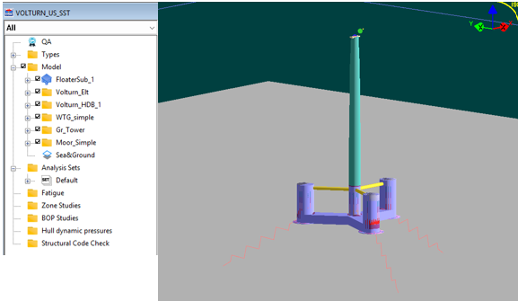
Figure 11 : Excel file imported in DLW GUI.
- 5 In DLW, click on HDB viewer and select the single floater tab. Then select the floater Volturn Us defined previously in the excel file and select the substructure motion type. Then create files and calculate the HDB. The calculation is taking a lot of time for this mesh. This part will generate the first order loads based on the floater's mesh. It is also possible to compute the second order loads (the drift forces and moments).
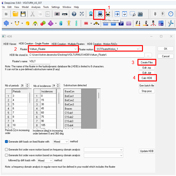
Figure 12 : HDB creation.
- 6 Once the HDB is created, displace it in the appropriate folder (the one defined in Floater definition).
Your model is now ready to run.
APPENDIX 1 FAIRLEADS
| Name | Object reference | Attach point name | Coordinates system | X (m) | Y (m) | Center X (m) | Center Y (m) | R (m) | Theta (deg) | Z (m) |
|---|---|---|---|---|---|---|---|---|---|---|
| FL_SeaAndGround | Sea&Ground | Anchor1 | Cylindrical | 700 | -81.6 | |||||
| FL_SeaAndGround | Sea&Ground | Anchor2 | Cylindrical | 700 | 120 | -81.6 | ||||
| FL_SeaAndGround | Sea&Ground | Anchor3 | Cylindrical | 700 | 240 | -81.6 | ||||
| FL_Volturn_Floater | Volturn_Floater | Centre | 0 | 0 | 0 | |||||
| FL_RB_BaseCC | RB_BaseCC | Center | 0 | 0 | 0 | |||||
| FL_RB_BaseCC | RB_BaseCC | CC-COL1 | 6 | 0 | 0 | |||||
| FL_RB_BaseCC | RB_BaseCC | CC-COL2 | -3 | 5.196152 | 0 | |||||
| FL_RB_BaseCC | RB_BaseCC | CC-COL3 | -3 | -5.196152 | 0 | |||||
| FL_RB_BaseCC | RB_BaseCC | CC-CC | 0 | 0 | 3.75 | |||||
| FL_RB_BaseCC | RB_BaseCC | Mesh | 0 | 0 | 14.75 | |||||
| FL_RB_BotCol1 | RB_BotCol1 | Skirt11 | 0 | 0 | -3.75 | |||||
| FL_RB_BotCol1 | RB_BotCol1 | Skirt12 | 0 | 0 | -3.35 | |||||
| FL_RB_BotCol1 | RB_BotCol1 | Center1 | 0 | 0 | 0 | |||||
| FL_RB_BotCol1 | RB_BotCol1 | BotCol1 | 0 | 0 | 3.75 | |||||
| FL_RB_BotCol1 | RB_BotCol1 | Pont1 | -8 | 0 | 0 | |||||
| FL_RB_BotCol1 | RB_BotCol1 | Mesh | -43 | 0 | 14.75 | |||||
| FL_RB_BotCol1 | RB_BotCol1 | Bal | 0 | 0 | -0.87 | |||||
| FL_RB_BotCol1 | RB_BotCol1 | Mooring | 7.25 | 0 | -1.75 | |||||
| FL_RB_BotCol2 | RB_BotCol2 | Skirt21 | 0 | 0 | -3.75 | |||||
| FL_RB_BotCol2 | RB_BotCol2 | Skirt22 | 0 | 0 | -3.35 | |||||
| FL_RB_BotCol2 | RB_BotCol2 | Center2 | 0 | 0 | 0 | |||||
| FL_RB_BotCol2 | RB_BotCol2 | BotCol2 | 0 | 0 | 3.75 | |||||
| FL_RB_BotCol2 | RB_BotCol2 | Pont2 | 4 | -6.928203 | 0 | |||||
| FL_RB_BotCol2 | RB_BotCol2 | Mesh | 21.5 | -37 | 14.75 | |||||
| FL_RB_BotCol2 | RB_BotCol2 | Bal | 0 | 0 | -0.87 | |||||
| FL_RB_BotCol2 | RB_BotCol2 | Mooring | -3.625 | 6.279 | -1.75 | |||||
| FL_RB_BotCol3 | RB_BotCol3 | Skirt31 | 0 | 0 | -3.75 | |||||
| FL_RB_BotCol3 | RB_BotCol3 | Skirt32 | 0 | 0 | -3.35 | |||||
| FL_RB_BotCol3 | RB_BotCol3 | Center3 | 0 | 0 | 0 | |||||
| FL_RB_BotCol3 | RB_BotCol3 | BotCol3 | 0 | 0 | 3.75 | |||||
| FL_RB_BotCol3 | RB_BotCol3 | Pont3 | 4 | 6.928203 | 0 | |||||
| FL_RB_BotCol3 | RB_BotCol3 | Mesh | 21.5 | 37 | 14.75 | |||||
| FL_RB_BotCol3 | RB_BotCol3 | Bal | 0 | 0 | -0.87 | |||||
| FL_RB_BotCol3 | RB_BotCol3 | Mooring | -3.625 | -6.279 | -1.75 | |||||
| FL_RB_TopCC | RB_TopCC | CC | 0 | 0 | 0 | |||||
| FL_RB_TopCC | RB_TopCC | Brace1 | 5 | 0 | 0 | |||||
| FL_RB_TopCC | RB_TopCC | Brace2 | -2.5 | 4.330127 | 0 | |||||
| FL_RB_TopCC | RB_TopCC | Brace3 | -2.5 | -4.330127 | 0 | |||||
| FL_RB_TopCol1 | RB_TopCol1 | Brace1 | -7.25 | 0 | 0 | |||||
| FL_RB_TopCol1 | RB_TopCol1 | Col1 | 0 | 0 | 0 | |||||
| FL_RB_TopCol2 | RB_TopCol2 | Brace2 | 3.625 | -6.278684 | 0 | |||||
| FL_RB_TopCol2 | RB_TopCol2 | Col2 | 0 | 0 | 0 | |||||
| FL_RB_TopCol3 | RB_TopCol3 | Brace3 | 3.625 | 6.278684 | 0 | |||||
| FL_RB_TopCol3 | RB_TopCol3 | Col3 | 0 | 0 | 0 | |||||
| FL_RG_WTG_simple | RG_WTG_simple | TowerConnection | 0 | 0 | 0 | |||||
| FL_RG_WTG_simple | RG_WTG_simple | CoGravity | 7.019 | 0 | 4.115 | |||||
| FL_RG_WTG_simple | RG_WTG_simple | hub-low | 10.604 | 0 | 4.962 | |||||
| FL_RG_WTG_simple | RG_WTG_simple | hub-high | 10.604 | 0 | 5.962 |
** Appendix 2 section
| Line reference | Name | Shape | Point 1 name | X 1 | Y 1 | Z 1 | Linked to 1 reference | Attach point 1 reference | Connection 1 type | Connection 1 reference | Point 2 name | X 2 | Y 2 | Z 2 | Linked to 2 reference | Attach point 2 reference | Connection 2 type | Connection 2 reference |
|---|---|---|---|---|---|---|---|---|---|---|---|---|---|---|---|---|---|---|
| CCentral | CCentral_Sect_1 | Straight | CC_center | RB_BaseCC | Center | User-defined | UDC_0 | BotCC | RB_BaseCC | CC-CC | User-defined | UDC_0 | ||||||
| CCentral | CCentral_Sect_2 | Straight | BotCC | RB_BaseCC | CC-CC | User-defined | UDC_0 | CC_2 | 0 | 0 | -5.94 | |||||||
| CCentral | CCentral_Sect_3 | Straight | CC_2 | 0 | 0 | -5.94 | CC_3 | 0 | 0 | -0.88 | ||||||||
| CCentral | CCentral_Sect_4 | Straight | CC_3 | 0 | 0 | -0.88 | CC_4 | 0 | 0 | 4.18 | ||||||||
| CCentral | CCentral_Sect_5 | Straight | CC_4 | 0 | 0 | 4.18 | CC_5 | 0 | 0 | 9.24 | ||||||||
| CCentral | CCentral_Sect_6 | Straight | CC_5 | 0 | 0 | 9.24 | Brace | RB_TopCC | CC | User-defined | UDC_0 | |||||||
| CCentral | CCentral_Sect_7 | Straight | Brace | RB_TopCC | CC | User-defined | UDC_0 | TopCC | 0 | 0 | 14.3 | |||||||
| CCentral | CCentral_Sect_8 | Straight | TopCC | 0 | 0 | 14.3 | BotTower | 0 | 0 | 15 | ||||||||
| CExt1 | CExt1_Sect_1 | Straight | Center1 | RB_BotCol1 | Center1 | User-defined | UDC_0 | BotCol1 | RB_BotCol1 | BotCol1 | User-defined | UDC_0 | ||||||
| CExt1 | CExt1_Sect_2 | Straight | BotCol1 | RB_BotCol1 | BotCol1 | User-defined | UDC_0 | Col1_2 | 43 | 0 | -5.94 | |||||||
| CExt1 | CExt1_Sect_3 | Straight | Col1_2 | 43 | 0 | -5.94 | Col1_3 | 43 | 0 | -0.88 | ||||||||
| CExt1 | CExt1_Sect_4 | Straight | Col1_3 | 43 | 0 | -0.88 | Col1_4 | 43 | 0 | 4.18 | ||||||||
| CExt1 | CExt1_Sect_5 | Straight | Col1_4 | 43 | 0 | 4.18 | Col1_5 | 43 | 0 | 9.24 | ||||||||
| CExt1 | CExt1_Sect_6 | Straight | Col1_5 | 43 | 0 | 9.24 | Brace1 | RB_TopCol1 | Col1 | User-defined | UDC_0 | |||||||
| CExt1 | CExt1_Sect_7 | Straight | Brace1 | RB_TopCol1 | Col1 | User-defined | UDC_0 | TopC1 | 43 | 0 | 14.3 | |||||||
| CExt2 | CExt2_Sect_1 | Straight | Center2 | RB_BotCol2 | Center2 | User-defined | UDC_0 | BotCol2 | RB_BotCol2 | BotCol2 | User-defined | UDC_0 | ||||||
| CExt2 | CExt2_Sect_2 | Straight | BotCol2 | RB_BotCol2 | BotCol2 | User-defined | UDC_0 | Col2_2 | -21.5 | 37.239 | -5.94 | |||||||
| CExt2 | CExt2_Sect_3 | Straight | Col2_2 | -21.5 | 37.239 | -5.94 | Col2_3 | -21.5 | 37.239 | -0.88 | ||||||||
| CExt2 | CExt2_Sect_4 | Straight | Col2_3 | -21.5 | 37.239 | -0.88 | Col2_4 | -21.5 | 37.239 | 4.18 | ||||||||
| CExt2 | CExt2_Sect_5 | Straight | Col2_4 | -21.5 | 37.239 | 4.18 | Col2_5 | -21.5 | 37.239 | 9.24 | ||||||||
| CExt2 | CExt2_Sect_6 | Straight | Col2_5 | -21.5 | 37.239 | 9.24 | Brace2 | RB_TopCol2 | Col2 | User-defined | UDC_0 | |||||||
| CExt2 | CExt2_Sect_7 | Straight | Brace2 | RB_TopCol2 | Col2 | User-defined | UDC_0 | TopC2 | -21.5 | 37.239 | 14.3 | |||||||
| CExt3 | CExt3_Sect_1 | Straight | Center3 | RB_BotCol3 | Center3 | User-defined | UDC_0 | BotCol3 | RB_BotCol3 | BotCol3 | User-defined | UDC_0 | ||||||
| CExt3 | CExt3_Sect_2 | Straight | BotCol3 | RB_BotCol3 | BotCol3 | User-defined | UDC_0 | Col3_2 | -21.5 | -37.239 | -5.94 | |||||||
| CExt3 | CExt3_Sect_3 | Straight | Col3_2 | -21.5 | -37.239 | -5.94 | Col3_3 | -21.5 | -37.239 | -0.88 | ||||||||
| CExt3 | CExt3_Sect_4 | Straight | Col3_3 | -21.5 | -37.239 | -0.88 | Col3_4 | -21.5 | -37.239 | 4.18 | ||||||||
| CExt3 | CExt3_Sect_5 | Straight | Col3_4 | -21.5 | -37.239 | 4.18 | Col3_5 | -21.5 | -37.239 | 9.24 | ||||||||
| CExt3 | CExt3_Sect_6 | Straight | Col3_5 | -21.5 | -37.239 | 9.24 | Brace3 | RB_TopCol3 | Col3 | User-defined | UDC_0 | |||||||
| CExt3 | CExt3_Sect_7 | Straight | Brace3 | RB_TopCol3 | Col3 | User-defined | UDC_0 | TopC3 | -21.5 | -37.339 | 14.3 | |||||||
| Pont1 | Pont1_Sect_1 | Straight | CC1 | RB_BaseCC | Center | User-defined | UDC_0 | CC_pont1 | RB_BaseCC | CC-COL1 | User-defined | UDC_0 | ||||||
| Pont1 | Pont1_Sect_2 | Straight | CC_pont1 | RB_BaseCC | CC-COL1 | User-defined | UDC_0 | CC1_2 | 9 | 0 | -14.75 | |||||||
| Pont1 | Pont1_Sect_3 | Straight | CC1_2 | 9 | 0 | -14.75 | CC1_3 | 12 | 0 | -14.75 | ||||||||
| Pont1 | Pont1_Sect_4 | Straight | CC1_3 | 12 | 0 | -14.75 | CC1_4 | 15 | 0 | -14.75 | ||||||||
| Pont1 | Pont1_Sect_5 | Straight | CC1_4 | 15 | 0 | -14.75 | CC1_5 | 19 | 0 | -14.75 | ||||||||
| Pont1 | Pont1_Sect_6 | Straight | CC1_5 | 19 | 0 | -14.75 | CC1_6 | 23 | 0 | -14.75 | ||||||||
| Pont1 | Pont1_Sect_7 | Straight | CC1_6 | 23 | 0 | -14.75 | CC1_7 | 27 | 0 | -14.75 | ||||||||
| Pont1 | Pont1_Sect_8 | Straight | CC1_7 | 27 | 0 | -14.75 | CC1_8 | 31 | 0 | -14.75 | ||||||||
| Pont1 | Pont1_Sect_9 | Straight | CC1_8 | 31 | 0 | -14.75 | Pont1 | RB_BotCol1 | Pont1 | User-defined | UDC_0 | |||||||
| Pont1 | Pont1_Sect_10 | Straight | Pont1 | RB_BotCol1 | Pont1 | User-defined | UDC_0 | Col1 | RB_BotCol1 | Center1 | User-defined | UDC_0 | ||||||
| Pont2 | Pont2_Sect_1 | Straight | CC2 | RB_BaseCC | Center | User-defined | UDC_0 | CC_pont2 | RB_BaseCC | CC-COL2 | User-defined | UDC_0 | ||||||
| Pont2 | Pont2_Sect_2 | Straight | CC_pont2 | RB_BaseCC | CC-COL2 | User-defined | UDC_0 | CC2_2 | -4.5 | 7.79422863 | -14.75 | |||||||
| Pont2 | Pont2_Sect_3 | Straight | CC2_2 | -4.5 | 7.79422863 | -14.75 | CC2_3 | -6 | 10.3923048 | -14.75 | ||||||||
| Pont2 | Pont2_Sect_4 | Straight | CC2_3 | -6 | 10.3923048 | -14.75 | CC2_4 | -7.5 | 12.9903811 | -14.75 | ||||||||
| Pont2 | Pont2_Sect_5 | Straight | CC2_4 | -7.5 | 12.9903811 | -14.75 | CC2_5 | -9.5 | 16.4544827 | -14.75 | ||||||||
| Pont2 | Pont2_Sect_6 | Straight | CC2_5 | -9.5 | 16.4544827 | -14.75 | CC2_6 | -11.5 | 19.9185843 | -14.75 | ||||||||
| Pont2 | Pont2_Sect_7 | Straight | CC2_6 | -11.5 | 19.9185843 | -14.75 | CC2_7 | -13.5 | 23.3826859 | -14.75 | ||||||||
| Pont2 | Pont2_Sect_8 | Straight | CC2_7 | -13.5 | 23.3826859 | -14.75 | CC2_8 | -15.5 | 26.8467875 | -14.75 | ||||||||
| Pont2 | Pont2_Sect_9 | Straight | CC2_8 | -15.5 | 26.8467875 | -14.75 | Pont2 | RB_BotCol2 | Pont2 | User-defined | UDC_0 | |||||||
| Pont2 | Pont2_Sect_10 | Straight | Pont2 | RB_BotCol2 | Pont2 | User-defined | UDC_0 | Col2 | RB_BotCol2 | Center2 | User-defined | UDC_0 | ||||||
| Pont3 | Pont3_Sect_1 | Straight | CC3 | RB_BaseCC | Center | User-defined | UDC_0 | CC_pont3 | RB_BaseCC | CC-COL3 | User-defined | UDC_0 | ||||||
| Pont3 | Pont3_Sect_2 | Straight | CC_pont3 | RB_BaseCC | CC-COL3 | User-defined | UDC_0 | CC3_2 | -4.5 | -7.79422863 | -14.75 | |||||||
| Pont3 | Pont3_Sect_3 | Straight | CC3_2 | -4.5 | -7.79422863 | -14.75 | CC3_3 | -6 | -10.3923048 | -14.75 | ||||||||
| Pont3 | Pont3_Sect_4 | Straight | CC3_3 | -6 | -10.3923048 | -14.75 | CC3_4 | -7.5 | -12.9903811 | -14.75 | ||||||||
| Pont3 | Pont3_Sect_5 | Straight | CC3_4 | -7.5 | -12.9903811 | -14.75 | CC3_5 | -9.5 | -16.4544827 | -14.75 | ||||||||
| Pont3 | Pont3_Sect_6 | Straight | CC3_5 | -9.5 | -16.4544827 | -14.75 | CC3_6 | -11.5 | -19.9185843 | -14.75 | ||||||||
| Pont3 | Pont3_Sect_7 | Straight | CC3_6 | -11.5 | -19.9185843 | -14.75 | CC3_7 | -13.5 | -23.3826859 | -14.75 | ||||||||
| Pont3 | Pont3_Sect_8 | Straight | CC3_7 | -13.5 | -23.3826859 | -14.75 | CC3_8 | -15.5 | -26.8467875 | -14.75 | ||||||||
| Pont3 | Pont3_Sect_9 | Straight | CC3_8 | -15.5 | -26.8467875 | -14.75 | Pont3 | RB_BotCol3 | Pont3 | User-defined | UDC_0 | |||||||
| Pont3 | Pont3_Sect_10 | Straight | Pont3 | RB_BotCol3 | Pont3 | User-defined | UDC_0 | Col3 | RB_BotCol3 | Center3 | User-defined | UDC_0 | ||||||
| Skirt1 | Skirt1_Sect_1 | Straight | BotSk1 | RB_BotCol1 | Skirt11 | User-defined | UDC_0 | TopSk1 | RB_BotCol1 | Skirt12 | User-defined | UDC_0 | ||||||
| Skirt2 | Skirt2_Sect_1 | Straight | BotSk2 | RB_BotCol2 | Skirt21 | User-defined | UDC_0 | TopSk2 | RB_BotCol2 | Skirt22 | User-defined | UDC_0 | ||||||
| Skirt3 | Skirt3_Sect_1 | Straight | BotSk3 | RB_BotCol3 | Skirt31 | User-defined | UDC_0 | TopSk3 | RB_BotCol3 | Skirt32 | User-defined | UDC_0 | ||||||
| Brace1 | Brace1_Sect_1 | Straight | CC1 | RB_TopCC | Brace1 | User-defined | UDC_0 | Col1 | RB_TopCol1 | Brace1 | User-defined | UDC_0 | ||||||
| Brace2 | Brace2_Sect_1 | Straight | CC2 | RB_TopCC | Brace2 | User-defined | UDC_0 | Col2 | RB_TopCol2 | Brace2 | User-defined | UDC_0 | ||||||
| Brace3 | Brace3_Sect_1 | Straight | CC3 | RB_TopCC | Brace3 | User-defined | UDC_0 | Col3 | RB_TopCol3 | Brace3 | User-defined | UDC_0 | ||||||
| aero_WTG | aero_WTG_Sect_1 | Straight | Down | RG_WTG_simple | hub-low | User-defined | UDC_0 | Up | RG_WTG_simple | hub-high | User-defined | UDC_0 | ||||||
| Tower | Tower_Sect_1 | Straight | End_Down | CCentral | BotTower | User-defined | UDC_0 | YawB | 0 | 0 | 143.582 |
** Appendix 3 segment
| Section reference | Name | Length (m) | Target element length (m) | Number of elements | Segment type reference |
|---|---|---|---|---|---|
| CCentral_Sect_1 | SecCC_fake | 3.75 | 1 | CC_fake | |
| CCentral_Sect_2 | CCSUB1 | 5.06 | 1 | CCpro1 | |
| CCentral_Sect_3 | CCSUB2 | 5.06 | 1 | CCpro2 | |
| CCentral_Sect_4 | CCSUB3 | 5.06 | 1 | CCpro3 | |
| CCentral_Sect_5 | CCSUB4 | 5.06 | 1 | CCpro4 | |
| CCentral_Sect_6 | CCSUB5 | 2.06 | 1 | CCpro5 | |
| CCentral_Sect_7 | TopCC | 3 | 1 | CCpro6 | |
| CCentral_Sect_8 | Transition | 0.7 | 1 | Transipro | |
| CExt1_Sect_1 | BotC1 | 3.75 | 1 | Cext_fake | |
| CExt1_Sect_2 | C1SUB1 | 5.06 | 1 | Cextpro1 | |
| CExt1_Sect_3 | C1SUB2 | 5.06 | 1 | Cextpro2 | |
| CExt1_Sect_4 | C1SUB3 | 5.06 | 1 | Cextpro3 | |
| CExt1_Sect_5 | C1SUB4 | 5.06 | 1 | Cextpro4 | |
| CExt1_Sect_6 | C1SUB5 | 2.06 | 1 | Cextpro5 | |
| CExt1_Sect_7 | TopC1 | 3 | 1 | Cextpro6 | |
| CExt2_Sect_1 | BotC2 | 3.75 | 1 | Cext_fake | |
| CExt2_Sect_2 | C2SUB1 | 5.06 | 1 | Cextpro1 | |
| CExt2_Sect_3 | C2SUB2 | 5.06 | 1 | Cextpro2 | |
| CExt2_Sect_4 | C2SUB3 | 5.06 | 1 | Cextpro3 | |
| CExt2_Sect_5 | C2SUB4 | 5.06 | 1 | Cextpro4 | |
| CExt2_Sect_6 | C2SUB5 | 2.06 | 1 | Cextpro5 | |
| CExt2_Sect_7 | TopC2 | 3 | 1 | Cextpro6 | |
| CExt3_Sect_1 | BotC2 | 3.75 | 1 | Cext_fake | |
| CExt3_Sect_2 | C3SUB1 | 5.06 | 1 | Cextpro1 | |
| CExt3_Sect_3 | C3SUB2 | 5.06 | 1 | Cextpro2 | |
| CExt3_Sect_4 | C3SUB3 | 5.06 | 1 | Cextpro3 | |
| CExt3_Sect_5 | C3SUB4 | 5.06 | 1 | Cextpro4 | |
| CExt3_Sect_6 | C3SUB5 | 2.06 | 1 | Cextpro5 | |
| CExt3_Sect_7 | TopC2 | 3 | 1 | Cextpro6 | |
| Pont1_Sect_1 | Pon1CC | 6 | 1 | ponton_fake | |
| Pont1_Sect_2 | Pon1SUB1 | 4 | 1 | pontonpro1 | |
| Pont1_Sect_3 | Pon1SUB2 | 4 | 1 | pontonpro2 | |
| Pont1_Sect_4 | Pon1SUB3 | 4 | 1 | pontonpro3 | |
| Pont1_Sect_5 | Pon1SUB4 | 4 | 1 | pontonpro4 | |
| Pont1_Sect_6 | Pon1SUB5 | 4 | 1 | pontonpro5 | |
| Pont1_Sect_7 | Pon1SUB6 | 3 | 1 | pontonpro6 | |
| Pont1_Sect_8 | Pon1SUB7 | 3 | 1 | pontonpro7 | |
| Pont1_Sect_9 | Pon1SUB8 | 3 | 1 | pontonpro8 | |
| Pont1_Sect_10 | Pon1COL1 | 8 | 1 | ponton_fake | |
| Pont2_Sect_1 | Pon2CC | 6 | 1 | ponton_fake | |
| Pont2_Sect_2 | Pon2SUB1 | 4 | 1 | pontonpro1 | |
| Pont2_Sect_3 | Pon2SUB2 | 4 | 1 | pontonpro2 | |
| Pont2_Sect_4 | Pon2SUB3 | 4 | 1 | pontonpro3 | |
| Pont2_Sect_5 | Pon2SUB4 | 4 | 1 | pontonpro4 | |
| Pont2_Sect_6 | Pon2SUB5 | 4 | 1 | pontonpro5 | |
| Pont2_Sect_7 | Pon2SUB6 | 3 | 1 | pontonpro6 | |
| Pont2_Sect_8 | Pon2SUB7 | 3 | 1 | pontonpro7 | |
| Pont2_Sect_9 | Pon2SUB8 | 3 | 1 | pontonpro8 | |
| Pont2_Sect_10 | Pon2COL2 | 8 | 1 | ponton_fake | |
| Pont3_Sect_1 | Pon3CC | 6 | 1 | ponton_fake | |
| Pont3_Sect_2 | Pon3SUB1 | 4 | 1 | pontonpro1 | |
| Pont3_Sect_3 | Pon3SUB2 | 4 | 1 | pontonpro2 | |
| Pont3_Sect_4 | Pon3SUB3 | 4 | 1 | pontonpro3 | |
| Pont3_Sect_5 | Pon3SUB4 | 4 | 1 | pontonpro4 | |
| Pont3_Sect_6 | Pon3SUB5 | 4 | 1 | pontonpro5 | |
| Pont3_Sect_7 | Pon3SUB6 | 3 | 1 | pontonpro6 | |
| Pont3_Sect_8 | Pon3SUB7 | 3 | 1 | pontonpro7 | |
| Pont3_Sect_9 | Pon3SUB8 | 3 | 1 | pontonpro8 | |
| Pont3_Sect_10 | Pon3COL3 | 8 | 1 | ponton_fake | |
| Skirt1_Sect_1 | SKT1 | 0.4 | 1 | skirtpro | |
| Skirt2_Sect_1 | SKT2 | 0.4 | 1 | skirtpro | |
| Skirt3_Sect_1 | SKT3 | 0.4 | 1 | skirtpro | |
| Brace1_Sect_1 | Br1 | 30.75 | 2 | Bracepro | |
| Brace2_Sect_1 | Br2 | 30.75 | 2 | Bracepro | |
| Brace3_Sect_1 | Br3 | 30.75 | 2 | Bracepro | |
| aero_WTG_Sect_1 | seg1 | 1 | 1 | aeropro | |
| Tower_Sect_1 | seg_1 | 13 | 4 | Tower_S1 | |
| Tower_Sect_1 | seg_2 | 13 | 4 | Tower_S2 | |
| Tower_Sect_1 | seg_3 | 13 | 4 | Tower_S3 | |
| Tower_Sect_1 | seg_4 | 13 | 4 | Tower_S4 | |
| Tower_Sect_1 | seg_5 | 13 | 4 | Tower_S5 | |
| Tower_Sect_1 | seg_6 | 13 | 4 | Tower_S6 | |
| Tower_Sect_1 | seg_7 | 13 | 4 | Tower_S7 | |
| Tower_Sect_1 | seg_8 | 13 | 4 | Tower_S8 | |
| Tower_Sect_1 | seg_9 | 13 | 4 | Tower_S9 | |
| Tower_Sect_1 | seg_10 | 11.582 | 3 | Tower_S10 |
** Appendix 4 generic lines
| Name | Lineic mass (kg/m) | Axial stiffness (N) | Bending stiffness in local axis X (N.m2) | Bending stiffness in local axis Y (N.m2) | Torsion stiffness (N.m2/rad) | Shear stiffness in local axis X (N) | Shear stiffness in local axis Y (N) | Polar inertia X (kg.m) | Polar inertia Y (kg.m) | Polar inertia Z (kg.m) | Internal cross section (mm2) | End cap effect area (mm2) | Buoyancy area (mm2) |
|---|---|---|---|---|---|---|---|---|---|---|---|---|---|
| CCpro1 | 3.02E+04 | 4.83E+11 | 5.57E+12 | 5.57E+12 | 4.64E+12 | 4.02E+11 | 4.02E+11 | 3.48E+05 | 3.48E+05 | 6.96E+05 | 6.65E+04 | 7.85E+07 | 7.85E+07 |
| CCpro2 | 3.02E+04 | 4.83E+11 | 5.57E+12 | 5.57E+12 | 4.64E+12 | 4.02E+11 | 4.02E+11 | 3.48E+05 | 3.48E+05 | 6.96E+05 | 6.65E+04 | 7.85E+07 | 7.85E+07 |
| CCpro3 | 3.02E+04 | 4.83E+11 | 5.57E+12 | 5.57E+12 | 4.64E+12 | 4.02E+11 | 4.02E+11 | 3.48E+05 | 3.48E+05 | 6.96E+05 | 6.65E+04 | 7.85E+07 | 7.85E+07 |
| CCpro4 | 3.02E+04 | 4.83E+11 | 5.57E+12 | 5.57E+12 | 4.64E+12 | 4.02E+11 | 4.02E+11 | 3.48E+05 | 3.48E+05 | 6.96E+05 | 6.65E+04 | 7.85E+07 | 7.85E+07 |
| CCpro5 | 3.02E+04 | 4.83E+11 | 5.57E+12 | 5.57E+12 | 4.64E+12 | 4.02E+11 | 4.02E+11 | 3.48E+05 | 3.48E+05 | 6.96E+05 | 6.65E+04 | 7.85E+07 | 7.85E+07 |
| CCpro6 | 3.02E+04 | 4.83E+11 | 5.57E+12 | 5.57E+12 | 4.64E+12 | 4.02E+11 | 4.02E+11 | 3.48E+05 | 3.48E+05 | 6.96E+05 | 6.65E+04 | 7.85E+07 | 7.85E+07 |
| Cextpro1 | 4.43E+04 | 7.09E+11 | 1.76E+13 | 1.76E+13 | 1.47E+13 | 5.91E+11 | 5.91E+11 | 1.10E+06 | 1.10E+06 | 2.20E+06 | 1.47E+05 | 1.65E+08 | 1.65E+08 |
| Cextpro2 | 4.43E+04 | 7.09E+11 | 1.76E+13 | 1.76E+13 | 1.47E+13 | 5.91E+11 | 5.91E+11 | 1.10E+06 | 1.10E+06 | 2.20E+06 | 1.47E+05 | 1.65E+08 | 1.65E+08 |
| Cextpro3 | 4.43E+04 | 7.09E+11 | 1.76E+13 | 1.76E+13 | 1.47E+13 | 5.91E+11 | 5.91E+11 | 1.10E+06 | 1.10E+06 | 2.20E+06 | 1.47E+05 | 1.65E+08 | 1.65E+08 |
| Cextpro4 | 4.43E+04 | 7.09E+11 | 1.76E+13 | 1.76E+13 | 1.47E+13 | 5.91E+11 | 5.91E+11 | 1.10E+06 | 1.10E+06 | 2.20E+06 | 1.47E+05 | 1.65E+08 | 1.65E+08 |
| Cextpro5 | 4.43E+04 | 7.09E+11 | 1.76E+13 | 1.76E+13 | 1.47E+13 | 5.91E+11 | 5.91E+11 | 1.10E+06 | 1.10E+06 | 2.20E+06 | 1.47E+05 | 1.65E+08 | 1.65E+08 |
| Cextpro6 | 4.43E+04 | 7.09E+11 | 1.76E+13 | 1.76E+13 | 1.47E+13 | 5.91E+11 | 5.91E+11 | 1.10E+06 | 1.10E+06 | 2.20E+06 | 1.47E+05 | 1.65E+08 | 1.65E+08 |
| pontonpro1 | 4.24E+04 | 6.78E+11 | 6.66E+12 | 1.88E+13 | 1.26E+13 | 5.65E+11 | 5.65E+11 | 4.16E+05 | 1.17E+06 | 9.45E+05 | 9.18E+04 | 1.09E+08 | 1.09E+08 |
| pontonpro2 | 4.24E+04 | 6.78E+11 | 6.66E+12 | 1.88E+13 | 1.26E+13 | 5.65E+11 | 5.65E+11 | 4.16E+05 | 1.17E+06 | 9.45E+05 | 9.18E+04 | 1.09E+08 | 1.09E+08 |
| pontonpro3 | 4.24E+04 | 6.78E+11 | 6.66E+12 | 1.88E+13 | 1.26E+13 | 5.65E+11 | 5.65E+11 | 4.16E+05 | 1.17E+06 | 9.45E+05 | 9.18E+04 | 1.09E+08 | 1.09E+08 |
| pontonpro4 | 4.24E+04 | 6.78E+11 | 6.66E+12 | 1.88E+13 | 1.26E+13 | 5.65E+11 | 5.65E+11 | 4.16E+05 | 1.17E+06 | 9.45E+05 | 9.18E+04 | 1.09E+08 | 1.09E+08 |
| pontonpro5 | 4.24E+04 | 6.78E+11 | 6.66E+12 | 1.88E+13 | 1.26E+13 | 5.65E+11 | 5.65E+11 | 4.16E+05 | 1.17E+06 | 9.45E+05 | 9.18E+04 | 1.09E+08 | 1.09E+08 |
| pontonpro6 | 4.24E+04 | 6.78E+11 | 6.66E+12 | 1.88E+13 | 1.26E+13 | 5.65E+11 | 5.65E+11 | 4.16E+05 | 1.17E+06 | 9.45E+05 | 9.18E+04 | 1.09E+08 | 1.09E+08 |
| pontonpro7 | 4.24E+04 | 6.78E+11 | 6.66E+12 | 1.88E+13 | 1.26E+13 | 5.65E+11 | 5.65E+11 | 4.16E+05 | 1.17E+06 | 9.45E+05 | 9.18E+04 | 1.09E+08 | 1.09E+08 |
| pontonpro8 | 4.24E+04 | 6.78E+11 | 6.66E+12 | 1.88E+13 | 1.26E+13 | 5.65E+11 | 5.65E+11 | 4.16E+05 | 1.17E+06 | 9.45E+05 | 9.18E+04 | 1.09E+08 | 1.09E+08 |
| skirtpro | 5.16E+05 | 1.07E+12 | 3.53E+14 | 3.53E+14 | 2.71E+14 | 8.94E+11 | 8.94E+11 | 2.20E+07 | 2.20E+07 | 4.41E+07 | 1.65E+02 | 3.72E+08 | 3.72E+08 |