Home > Model Components > Tubular joints Flexibilities and Stress Concentration Factors
Tubular joints : stiffnesses and Stress Concentration Factors
Subjoints
The expressions used to calculate stiffnesses or SCF are relative to the coplanar intersections of the tubes forming a joint. A subjoint is the set of braces and chords of the joint that are in the same plane, a joint can therefore have one or more sub-joints.
The subjoints of the joints belonging to a group of joints are automatically defined as explained below.
Subjoints objects
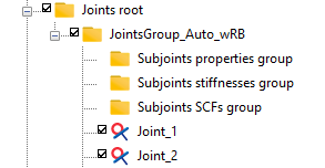
When creating a new group of joints, three subfolders are systematically and automatically added:
-
Subjoints properties group
-
Subjoints stiffnesses group
-
Subjoints SCFs group
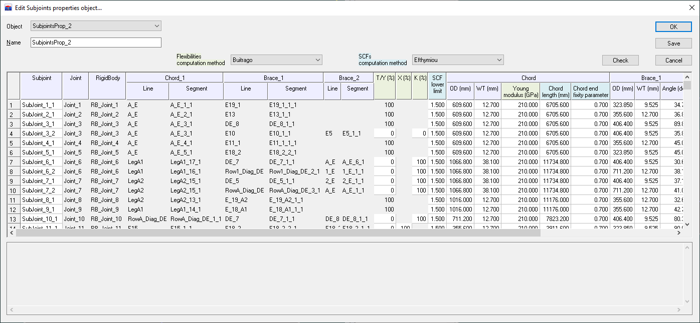
Creating an object in the properties group constructs automatically the subjoints and allows the user to assign the characteristics of the chords and braces forming the sub-joint, such as diameters and thicknesses. These properties are filled by default from the line type of the tube. The subjoints are created from the joints belonging to the same group and it is possible to define several properties objects allowing different datasets to be assigned to the tubes.
The process for assigning stiffnesses or SCF to subjoints is identical. There are two ways to proceed:
-
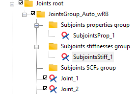
either drag a Subjoint properties object into one of the two others group (Subjoints stiffnesses group or Subjoints SCFs group): a new object is then created and the dialog box is automatically opened. For example, for a Subjoints stiffnesses object:
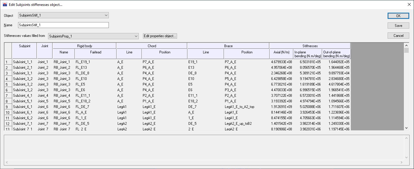
The stiffnesses or SCF are automatically calculated for each subjoint based on the properties assigned to the tubes in the properties object and their values are displayed in the last columns.
-
or use the New subjoints object item in the context menu of the relevant group (Subjoints stiffnesses group or Subjoints SCFs group), in which case the user can assign the stiffnesses or SCF values.
Regardless of the initial way chosen, it is possible to switch to the other way:
-
when the stiffnesses or SCF object is built by drag and drop from a properties object, the name of this properties object appears next to the title Properties object as shown before. In this case, the values of the stiffnesses or SCF cannot be changed by the user and the link between the subjoints properties object used to compute the values and the subjoints stiffnesses or SCFs object is saved. If the user wants to enter its own values, he must select the "User-defined" item from the dropdown list instead of the previously selected object. In that case, the link between the properties object is broken.
-
if the stiffnesses or SCFs object is created initially without the reference of a properties object, the user can enter its own values or he can choose the name of a properties object in the dropdown list. In this last case, the values are computed from the tubes properties defined in the properties object.
Stiffnesses
The stiffnesses attributed to the subjoints are calculated according to the Buitrago method described in the "APPENDIX A LOCAL JOINT FLEXIBILITIES FOR TUBULAR JOINTS" of the DNVGL-ST-0126 regulation document (April 2016).
Their computations depend on the tube properties (diameter and thickness), percentage of subjoint type (Y, X, K, KT) and gap(s) between braces for K-joint or KT-joint.
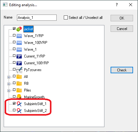
Stiffnesses are used by analyses launched by the solver. Once the Subjoints stiffnesses object has been created as explained in the previous section, it must be included in the analysis. This can be done by dragging the object into the analysis or selecting it from the list of objects assigned to the analysis:
Stress concentration factors
The SCF attributed to the subjoints are calculated according to the Efthymiou method described in the "APPENDIX B STRESS CONCENTRATION FACTORS FOR TUBULAR JOINTS" of the DNV-RP-C203 regulation document: Fatigue design of offshore steel structures (September 2021).
The validity of the Efthymiou's expressions assumes that geometrical parameters have values within ranges. The figure below gives the definition of these geometrical parameters.
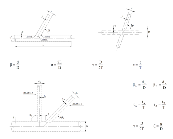
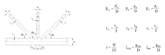
The validity ranges of these geometrical parameters are as follows:
Messages from the validity ranges for the Efthymiou parametric SCF equations are displayed in the area which receipts the output messages.
By default, the chord fixity parameter \(C\) has the value 0.5 and the chord length has the value \(L=6 D\) to avoid "double-dipping" as explained in section C5.3.2(b) of the API-RP-2A-WSD, 21st edition (2007).
The default value of the SCF lower limit is 1.5 as recommended by the API-RP-2A-WSD (2007) § 5.3.1.
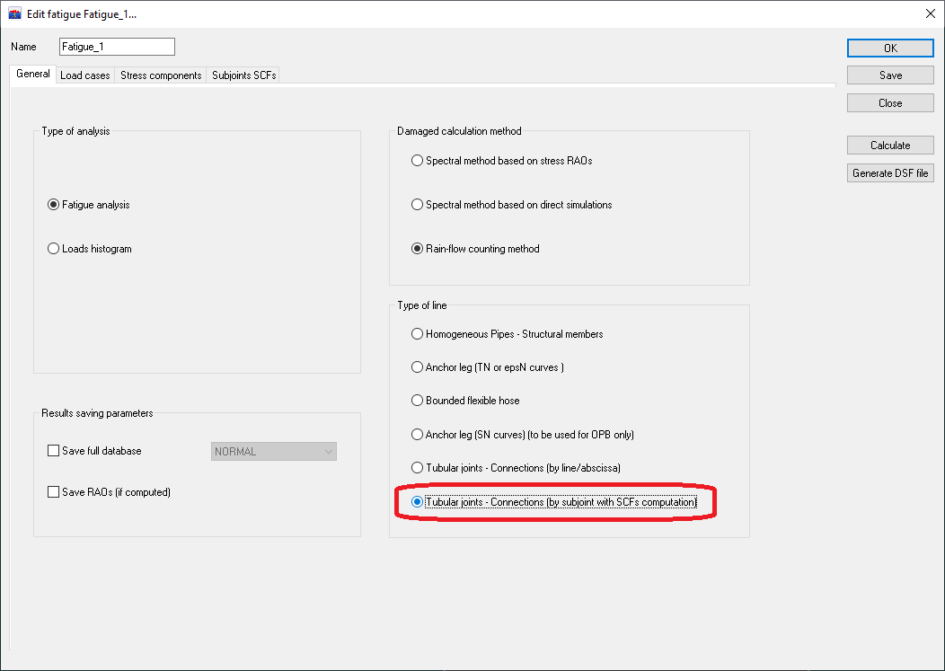
These SCF are used by fatigue study on tubular joints. Once the fatigue analysis has been created (see Fatigue analyses), the type of line Tubular joints - Connections (by subjoint with SCFs computation) must be selected as shown below.
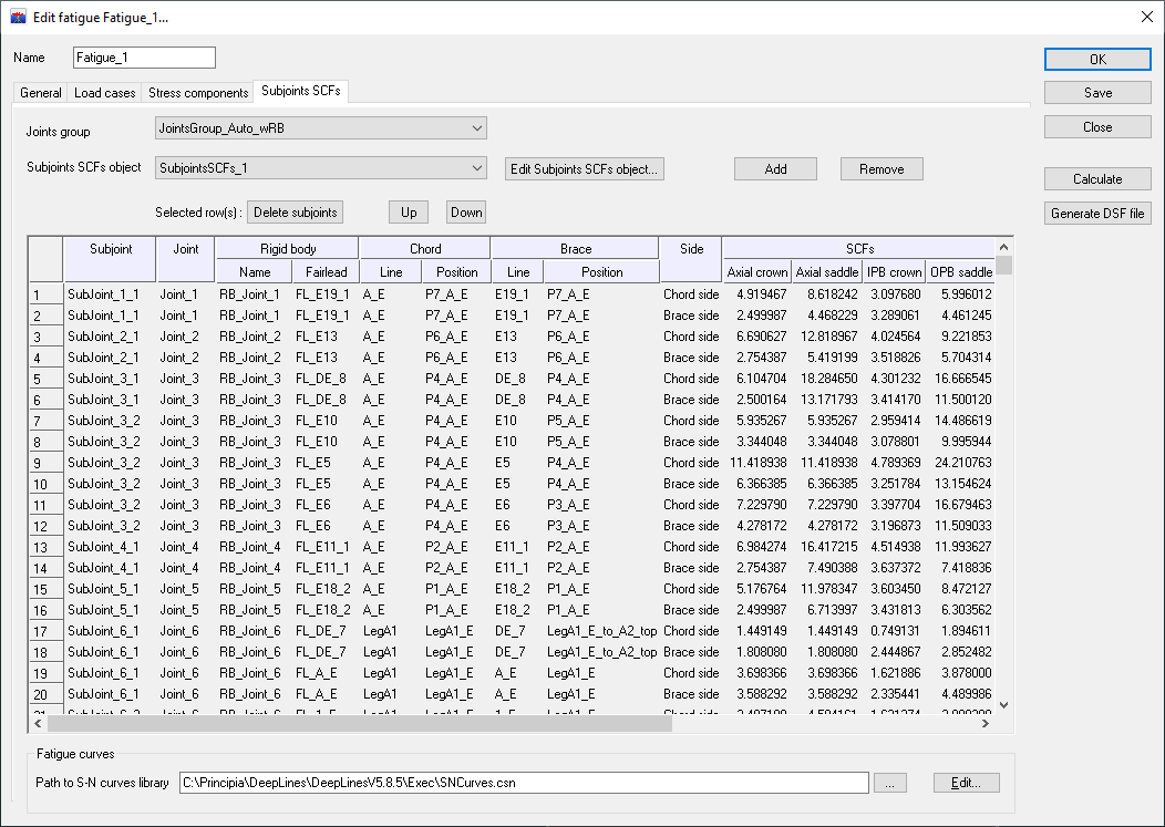
The joints participating in the study have to be chosen in the tab Subjoints SCFs:
In the Stress components tab, it is possible to take into account the "chord effect" for the SCF computation (chord crown only), as described in the section "C5.3 STRESS CONCENTRATION FACTORS / a. Evaluation of Hot Spot Stress Ranges" in the API-RP-2A-WSD regulation document (October 2007).
The results are distributed into two folders, one concerning calculations using SCF on the brace side (folder name with _BraceSide suffix) and the other calculations using SCF on the chord side (folder name with _ChordSide suffix). These two folders take the analysis study name as prefix. For each folder, the results are written in text files as described in the section Fatigue post-processing.