Home > User Interface > Overview > Hydrodynamic Database Files Creation
Hydrodynamic database files HDB creation
This module is invoked by clicking the  icon from the toolbar or from the floater properties window Motion tab.
On the second, third and fourth tab of the screen, a tool enables the creation of hydrodynamic databases for, respectively, single, multiple floaters and motion RAO objects using the potential flow solver Diodore. The Generic floater's mesh is imported from an external data file in the floater object (2 formats are possible, DeepLines native format, and Diodore native format).
icon from the toolbar or from the floater properties window Motion tab.
On the second, third and fourth tab of the screen, a tool enables the creation of hydrodynamic databases for, respectively, single, multiple floaters and motion RAO objects using the potential flow solver Diodore. The Generic floater's mesh is imported from an external data file in the floater object (2 formats are possible, DeepLines native format, and Diodore native format).
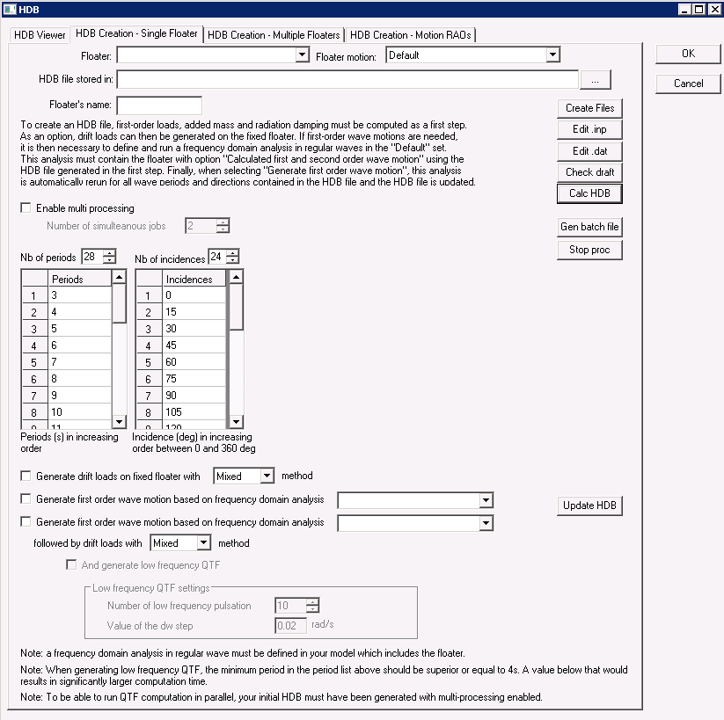
Figure 1 : HDB Creation - Single Floater.
Create HDB file with first order wave loads
To create HDB file with first order wave loads, user shall:
* create a generic floater
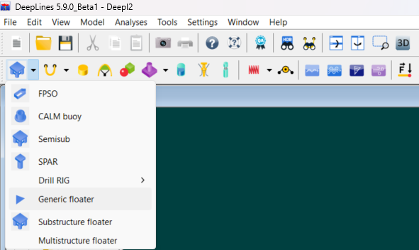
Figure 2 : Create a generic floater.
- associate a mesh to the generic floater
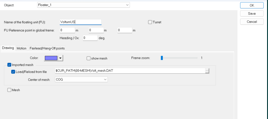
Figure 3 : Associate a mesh to the generic floater.
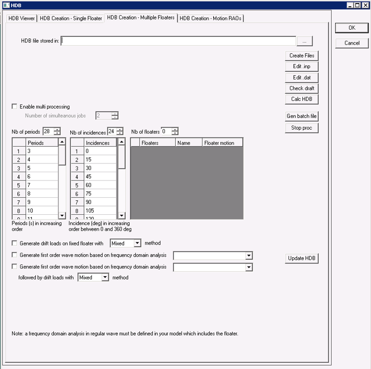
* fill the window HDB Creation - Single Floater/Multiple Floaters (see Figure 1).Once the floater is selected, it will update the HDB creation path accordingly, this can be further modified. The same goes for multiple floaters.
- as a useful check before generating the HDB file, you can click on "Check draft" to visualize the wetted mesh used to compute the HDB file. A window displays the mesh in water in blue and the mesh in air in red:
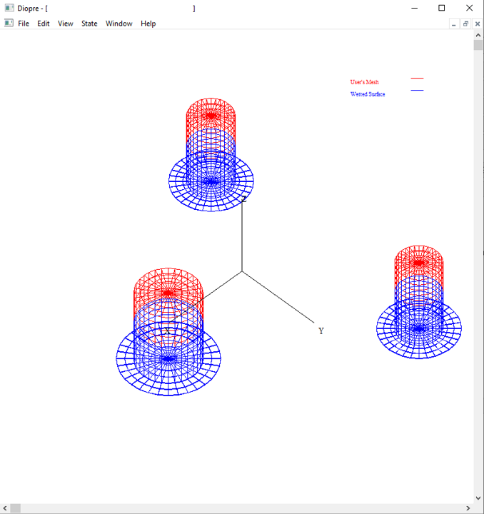
Figure 4 : Check draft.
- click on Calc HDB (see Figure 1)
Note
The Floater's name must not exceed 7 characters. The Floater's name is found in the mesh file for Diodore mesh format.
Commands available on window Figure 1
The following commands are available:
- Create Files : create the .inp and .dat files as input files for Diodore that will create the HDB file.
- Edit .inp : open the .inp file in an embedded editor to edit it manually.
- Edit .dat : open the .dat file in an embedded editor to edit it manually.
- Check draft : to visualize the wetted mesh used to compute the HDB file.
- Calc HDB : if not already created, it creates .inp and .dat files from the content of the mesh of the floater, then run Diodore process to create the .hdb file. Note that second order loads (drift forces and moments) can be obtained at this stage by clicking on the option "Generate second order loads on fixed floater"
- Gen batch file : creates .cmd files that contains commands which do the same as set on screen, for use outside DeepLines (by clicking on the .cmd file) or by loading in the batch processor
- Stop proc : stop any running creation process.
- Update HDB : if the HDB with first order load has been already created, this enables to update the HDB file with first order motions and also second order loads based on first order motion. Note that is possible only if a frequency domain analysis has been defined and previously run.
It is possible to run th HDB generation on multiple processors by cheking the box "Enable multi processing". Basically, each frequency is run independantly.
Note
Note that the calculations can be memory intensive so care should be used to not use too many processors.
Create HDB file with first and second order wave loads
The steps are:
1) Generate the first order loads based on the floater's mesh (as defined above)
2) In the floater motion type associated to the generic floater, the option "Calculated first and second order wave motion" must be selected in the "General panel", then in the "Calculated Motion" panel, select the HDB file crated in the first step together with the floater name
3) Define a frequency domain analysis in the "Default" analysis folder that includes the floater and a regular wave. All other components (mooring, loadings, turbine, ...) may be added. Then run the frequency domain analysis. If successful, go back to the HDB file creation panel and select the frequency domain analysis. It is now possible to update the HDB file.
The second order loads computed are the drift forces and moments. These loads are function of floater's response to the waves (first-order motion). Two options are available:
- Calculation of the drift loads with floater fixed
- Calculation of the drift including first order motion. This option requires as an input the first-order motion. This is obtained from frequency domain analysis.
Also, it is possible to derive the loads from the potential flow simulation with "Mixed" or "Pressure" method. With the "Pressure" method, drift forces are calculated by integration of pressures. With the "Mixed" method, the vertical directions are still computed with the "Pressure" method while the horizontal forces are obtained from the theorem of Lagally reformulated by Molin (A. Ledoux, B. Molin, G. Delhommeau, F. Remy. "A Lagally formulation of the wave drift force," 21st International Workshop Water Waves and Floating Bodies, Apr 2006, Loughborough, United Kingdom. pp.27.)
When computing the drift loads, second-order low frequency wave loads are computed in time domain base on Newman's approximation. It is also possible to compute the Quadratic Transfer Functions (QTFs). The QTFs are computed around the diagonal of the matrice for circular frequencies \(\omega_{1}=\omega_{2}\) or \(d\omega = 0\). This corresponds to the drift forces. The parameters entered are the number of low frequencies \(N\) and the circular frequency step \(\Delta \omega\). The QTFs are then computed at (\(\omega,\Delta \omega\)), with \(\Delta \omega\) varying form 0 to \(N \Delta \omega\). Note that the pulsation \(\omega\) are recomputed based on the input periods of the HDB files.
Note
Note that the accuracy of the hydrodynamic database and specifically of the second order loads is dependent on the quality of the mesh that is provided to DeepLines.
Note
The creation process can take a relatively long time if the mesh is complex. The "HDB" windows can be minimized and the user interface can still be used during the creation process. A log is displayed on the right side of the incidence definition control. It will keep you informed of the creation progress and steps. Do not close DeepLines' interface. Information can be found in the .MES files for the first order loads generation and some error message in GenRAO.day file for first order motion generation and drift.day for drift load generation. To speed up the generation process, the Enable multi processing option can be activated.
Note
Some other files are also copied next to the .HDB files. These files are created while generating the .HDB files that are used for post-treatment of the external pressure on the mesh.

Non-linear first order calculations can be performed with this .HDB file. When using this functionality, the hydrodynamic stiffness and first order froude-Krylov loads are automatically computed at the center of motion of the floater (depending on the selected option as defined in the "NL Loads" panel when "Use non-linear loads" is selected in the floater's motion). This point is defined in the floater motion type. The user must be careful if changing the floater motion type of a floater, or changing the property of the motion type, or using a different motion type for the floater in an analysis. The .HDB file that is generated is linked to the floater motion type and if it is modified, the .HDB file must be regenerated.
Warning
Also, the weight and inertia matrix are considered null in the .HDB file generated. A specific fairlead should then be defined in the floater's fairleads panel. A lump mass is created on this fairlead (for a diagonal inertia matrix) or a negative Z constant force for the weight together with a complete inertia matrix are loaded on this fairlead.
Note
This function was created to overcome problems often faced while linking an HDB file to a floater:
o Confusion between the Centre of gravity and Centre of motion defined in Deeplines model and the [CENTER OF GRAVITY] defined in the HDB
o Hydrostatic instability when the lever between the [CENTER OF GRAVITY] and the [CENTER OF BUOYANCY] is large.
o These problems have been highlighted when dealing with wind turbines since the global COG of the whole system is quite different from COG of the floating platform alone.
o Note that this can also happen for an installation barge loading with a heavy load…
The main idea is that the HDB creation is there to compute the diffraction/radiation loads on a ‘generic floater’ associated with a mesh.
The position of the mesh in Deeplines model fixes the draft for which the diffraction/radiation loads are computed.
An important point is that “diffraction/radiation loads” mean pressure loads coming from the fluid, the floater mass is not included at that stage, the hydrostatic stiffness in the HDB only refers to the restoring force coming from the fluid
The floater mass is defined in Deeplines model :
o For a simple floater, a lump mass and an inertia matrix may be ok,
o For more complex system, different elements connected to the floater will be part of this global mass (a crane, a wind turbine etc…)
In Deeplines, the option “non-linear hydrostatic loads” compute the hydrostatic stiffness, once the equilibrium is found and depending on the selected option it can be kept constant or updated during the time domain simulation as well as non linear Froud Krylov loads.
Create HDB file via command file
The calculation can be executed via a command file generated when clicking on the Gen batch file button. This command can be loaded in the batch tool.
Note
Note that if the option for generating RAOs or second order loads are selected, the generated batch command includes the whole chain from generation of the first order loads to second order loads. If the HDB file with first order loads is already generated the .cmd file can be edited to generate RAOs of motion only or drift forces only. The complete .cmd file is shown below with the various commands that are used.
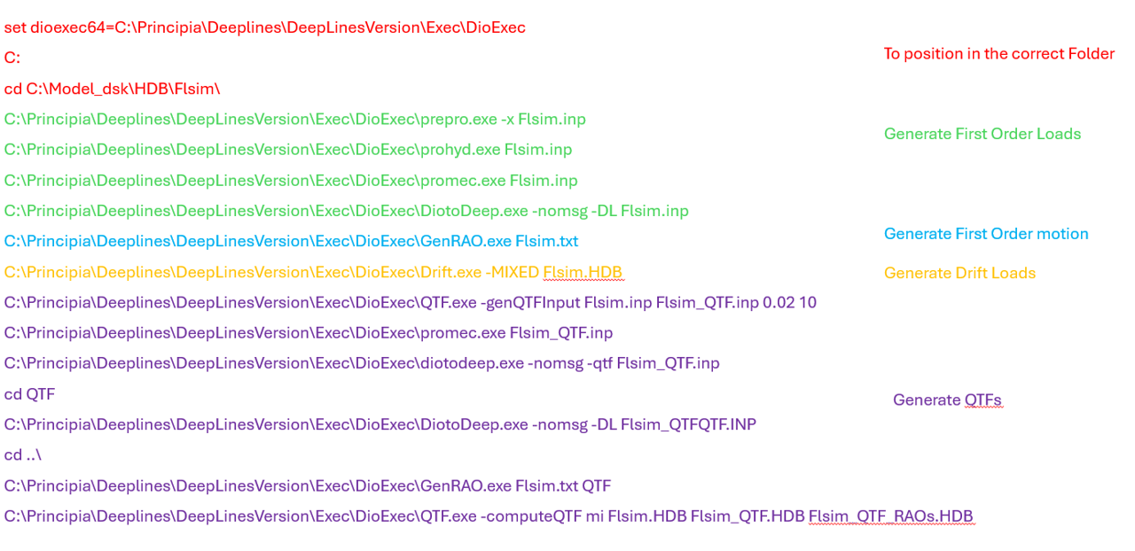 Figure 5 : Command file.
Note
Note that at least 1 period and 1 incidence should be filled to be able to launch the HDB creation process.
HDB for Substuctures
If the mesh used to generate the HDB files contains substructures, Diodore can generate information on each substructure for first order wave loads, added mass and radiation damping. Contrary to hydrodynamic coupling, all substructures move as a single body and not independently.
There are two possible modellings with substructures:
- A model where rigid elements are loaded with potential flow (HDB) loadings (plus drag coefficients if required), these rigid elements are linked by beam elements with hydrodynamic moading from Morsion formulation. This can be used for instance to compute hydrodynamic loads on different parts of a floater, to extract stresses in the connections between those elements.
- A model where all the elements are loaded with potential flow (HDB) loadings (plus drag coefficients if required)
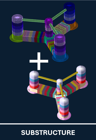
An example for the first type of modelling is shown in Figure "Structure and substructures". The floater is represented as a rigid structure in the left figure and an .HDB file of the whole floater is generated. If the objective is to define the floater as presented on the right with beam elements between the three outer columns to extract loads and stresses in the braces, then the external columns are defined as substructure during the hydrodynamic calculations.

Structure and substructures
To run the dynamic simulation in DeepLines, three floaters are defined pointing on the same HDB file but different substructure. To work properly:
- Mass/Inertia is defined for each substructure in DeepLines at substructures CoG,
- The mesh of each substructure independently is entered in DeepLines in order to recompute the hydrodynamic stiffness matrix,
- The reference node for the loads stored in the HDB is the same for all substructures as defined in the HDB files.
- The heading is the same for all substructures.
For the second type, an example with all element flexibles (except the four bottom connections) is presented in the figure below. The top mesh is the hydrodynamic mesh that is divided into the same section as the bottom structural mesh. Further details can be found in Model Components or Theory.
Hydrodynamic and Structural meshes
Warning
To determine rotation modes of systems composed of substructures, a rigidification must be applied. Rigidification has a small influence on translation modes. Then, rigidification must be used for systems composed of floater with motion RAOs. On the other hand for tower modes and floater deformation modes, rigidification should not be used.
HDB for multiple floaters - Hydrodynamic interaction between floaters
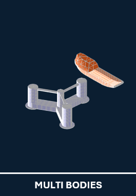
It is possible to generate HDB files with more than one floater to take into account the hydrodynamic interaction between those floaters. An example of Service Operational Vessel (SOV) close to a floater supporting a wind turbine is shown below. This can also be used for modelling Wake Energy Converters (WECs) with multiple floaters or floating solar farms.
A specific panel is used to define the floaters to be included in the hydrodynamic database. When using this hydrodynamic database for dynamic analysis, all the floaters used to generate the database should be present in your analysis. Note that specific coupling terms are generated (coupled added mass and radiation damping, see Theory).
Finally, it is possible to compute hydrodynamic interactions with a substructure model. If F1 is a floater with substructures while F2 is a floater with no substructure, the effect of F1 on F2 and F2 on F1 will be provided but also the effect of F2 on all substructures of F1. Note that to obtain the coupled hydrodynamic on the substructures, the floater with substructures must be the first floater entered in the panel above. If a floater other than the first one has substructures, no information on coupling effect on those substructures will be provided.
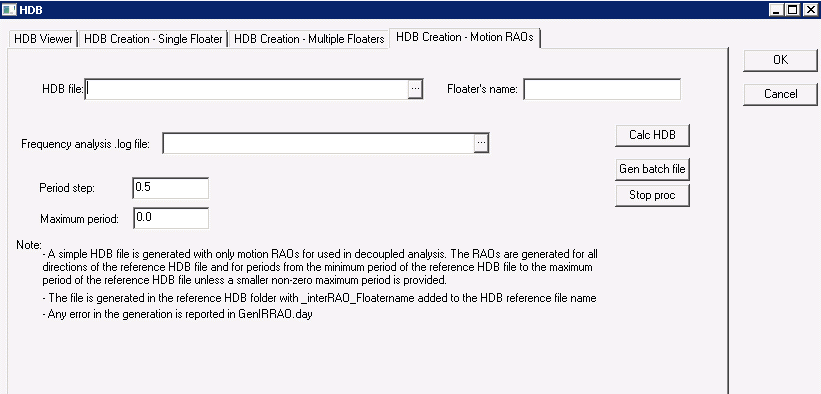
RAOs generation
It is also possible to generate simple HDB files with only motion RAOs. By providing:
* An HDB file generated on a floater (see above to generate an HDB file with first order wave loads),
* The name of the floater in the HDB files,
* A frequency domain analysis with the required wave height using the floater and HDB file.
A basic HDB file is created. This can be used to generate files for various wave heights. As the wave loads are interpolated between periods, make sure that the original database is properly discretized in periods.